
report.md 15 KB
Datacenter Network Simulation using Mininet实验报告
陈翊辉
SA19011116
[toc]
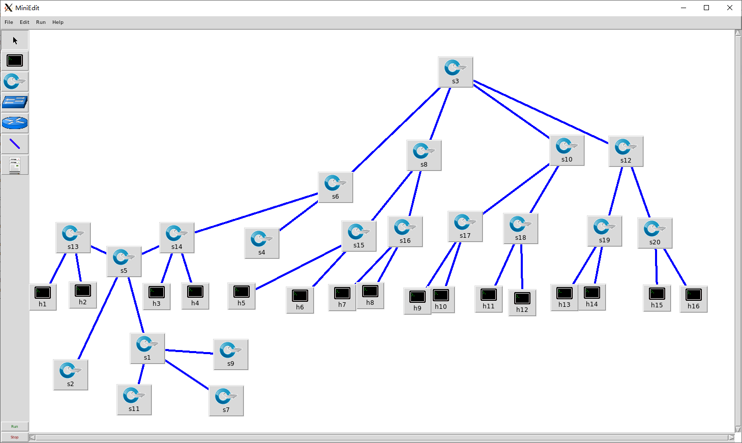
FatTree拓扑
使用16个host的fatTree拓扑如下图:

在实验时,使用miniedit拖放绘制拓扑,ip不设置,导出python文件src/fattree.py

实验环境和文件说明
实验环境
由于硬件,系统兼容性和性能等一些原因,没有使用实验提供的虚拟机环境,使用了GitHub仓库release中最新的版本
mininet image:https://github.com/mininet/mininet/releases/download/2.2.2/mininet-2.2.2-170321-ubuntu-14.04.4-server-amd64.zip
linux:Linux mininet-vm 4.2.0-27-generic #32~14.04.1-Ubuntu SMP
Python:Python 2.7.6 (default, Oct 26 2016, 20:30:19) [GCC 4.8.4] on linux2
wireshark:Version 1.10.6
MiniNet: 2.2.2
vm:Oracle VM VirtualBox 6.1.8
文件说明
.
├── report.pdf - 实验报告
├── result - 完整结果
│   ├── flowtable.txt - 实验1 link fail之前的流表
│   ├── flowtable_2.txt - 实验1 link fail之后的流表
│   ├── routetable.txt - 实验2路由表(根据论文中算法生成的路由表)
│   └── result.txt - 实验1 执行相关命令的输出
└── src
    ├── fattree.py - fattree的mininet topo,实验1和实验2共用
                    (实验2只要不启动控制器就相当于没有控制器)
    ├── flowtable.sh - 实验2配置流表的脚本,需要root权限
    └── lab1_commands.txt - 实验1相关命令(各命令需要一定时机使用,所有不放在脚本中)
实验一 使用POX控制器
程序代码
完整代码见src
def myNetwork():

    net = Mininet( topo=None,
                   build=False,
                   ipBase='10.0.0.0/8')

    info( '*** Adding controller\n' )
    c0=net.addController(name='c0',
                      controller=RemoteController,
                      ip='127.0.0.1',
                      protocol='tcp',
                      port=6633)

    info( '*** Add switches\n')
    s1 = net.addSwitch('s1', cls=OVSKernelSwitch)
    # ......
    s8 = net.addSwitch('s8', cls=OVSKernelSwitch)

    info( '*** Add hosts\n')
    h10 = net.addHost('h10', cls=Host, ip='10.0.0.10', defaultRoute=None)
    # ......
    h9 = net.addHost('h9', cls=Host, ip='10.0.0.9', defaultRoute=None)

    info( '*** Add links\n')
    net.addLink(s17, s1)
    # ......
    net.addLink(s20, s14)

    info( '*** Starting network\n')
    net.build()
    info( '*** Starting controllers\n')
    for controller in net.controllers:
        controller.start()

    info( '*** Starting switches\n')
    net.get('s1').start([c0])
    # ......
    net.get('s8').start([c0])

    info( '*** Post configure switches and hosts\n')

    CLI(net)
    net.stop()
启动后进入mininet的CLI,之后再进一步测试。
POX控制器设置
由于fattree拓扑结构中包含环,需要生成树(spanning tree),同时还需要learning,pox对两者支持都非常方便:
sudo ~/pox/pox.py forwarding.l2_learning \
  openflow.spanning_tree --no-flood --hold-down \
  log.level --DEBUG samples.pretty_log \
  openflow.discovery host_tracker \
  info.packet_dump
pingall测试
使用pingall测试结果,完整结果见result.txt
h10 -> h11 h4 h2 h13 h5 h16 h15 h14 h6 h7 h12 h8 h3 h1 h9
h11 -> h10 h4 h2 h13 h5 h16 h15 h14 h6 h7 h12 h8 h3 h1 h9
# ...
h9 -> h10 h11 h4 h2 h13 h5 h16 h15 h14 h6 h7 h12 h8 h3 h1
*** Results: 0% dropped (240/240 received)
可见所有主机之间可以连通
生成树结构
在上文的CLI环境中使用net和dpctl dump-ports-desc,输出如下,完整结果见result.txt
h10 h10-eth0:s11-eth4
h11 h11-eth0:s12-eth3
# ......
h9 h9-eth0:s11-eth3
s1 lo:  s1-eth1:s17-eth1 s1-eth2:s18-eth1 s1-eth3:s4-eth1 s1-eth4:s3-eth2
s7 lo:  s7-eth1:s6-eth1 s7-eth2:s5-eth4 s7-eth3:h5-eth0 s7-eth4:h6-eth0
# ......
s8 lo:  s8-eth1:s5-eth3 s8-eth2:s6-eth2 s8-eth3:h7-eth0 s8-eth4:h8-eth0
*** s19 ------------------------------------------------------------------------
OFPST_PORT_DESC reply (xid=0x2):
# ......
其中NO_FLOOD的端口即不使用的端口,由此结果可以绘制出生成树如下图:

这样看比较难看出是不是树,稍作调整,可以看出确实是树:

流表结果分析
(打印流表时需要注意在pingall之后一段时间流表会过期)
完整流表见flowtable.txt
s1
NXST_FLOW reply (xid=0x4):
 cookie=0x0, duration=3776.215s, table=0, n_packets=0, n_bytes=0, idle_age=3776, priority=32769,arp,dl_dst=02:00:00:00:be:ef actions=CONTROLLER:65535
 cookie=0x0, duration=3776.253s, table=0, n_packets=2536, n_bytes=103976, idle_age=2, priority=65000,dl_dst=01:23:20:00:00:01,dl_type=0x88cc actions=CONTROLLER:65535
s1的流表没有新增的项,原因是没有host间没有经过s1,这和上图的spanning tree结构符合;同理s2等的流表也没有新增
s3
完整流表见flowtable.txt中flowtable s3部分
NXST_FLOW reply (xid=0x4): flags=[more]
 cookie=0x0, duration=8.299s, table=0, n_packets=1, n_bytes=42, idle_timeout=10, hard_timeout=30, idle_age=8, priority=65535,arp,in_port=2,vlan_tci=0x0000,dl_src=be:ee:82:8e:83:b3,dl_dst=a6:a8:f5:50:0f:f5,arp_spa=10.0.0.6,arp_tpa=10.0.0.2,arp_op=1 actions=output:1
 cookie=0x0, duration=6.091s, table=0, n_packets=1, n_bytes=42, idle_timeout=10, hard_timeout=30, idle_age=6, priority=65535,arp,in_port=1,vlan_tci=0x0000,dl_src=46:b5:d8:3f:c6:49,dl_dst=fe:4a:73:99:00:4d,arp_spa=10.0.0.1,arp_tpa=10.0.0.5,arp_op=2 actions=output:2
 cookie=0x0, duration=7.604s, table=0, n_packets=1, n_bytes=42, idle_timeout=10, hard_timeout=30, idle_age=7, priority=65535,arp,in_port=2,vlan_tci=0x0000,dl_src=7a:88:6e:5a:92:e8,dl_dst=aa:bc:b6:32:73:36,arp_spa=10.0.0.7,arp_tpa=10.0.0.11,arp_op=2 actions=output:3
# ......
s3的流表项就非常多,记录了一项src,dst的action等信息,当然流表项也不会合并,总的结果和上图符合,也表明了确实有learning功能。其他有数据经过的交换机的流表也和s3类似,见flowtable.txt。
链路断开
断开如3根链路(s6-s13;s9-s15;s11-s20),使用CLI命令:
link s6 s13 down
link s11 s20 down
link s9 s15 down
在POX Controller可以观察到相关链接超时,并且spanning tree更新
[openflow.discovery     ] link timeout: 00-00-00-00-00-09.3 -> 00-00-00-00-00-11.1
[openflow.discovery     ] link timeout: 00-00-00-00-00-08.4 -> 00-00-00-00-00-10.2
[openflow.spanning_tree ] Spanning tree updated
[openflow.discovery     ] link timeout: 00-00-00-00-00-05.1 -> 00-00-00-00-00-01.1
[openflow.discovery     ] link timeout: 00-00-00-00-00-11.1 -> 00-00-00-00-00-09.3
[openflow.discovery     ] link timeout: 00-00-00-00-00-10.2 -> 00-00-00-00-00-08.4
[openflow.discovery     ] link timeout: 00-00-00-00-00-01.1 -> 00-00-00-00-00-05.1
[openflow.spanning_tree ] Spanning tree updated
[openflow.spanning_tree ] 4 ports changed
[openflow.spanning_tree ] Spanning tree updated
使用pingall测试,host间可以连通
mininet> pingall
*** Ping: testing ping reachability
h14 -> h15 h6 h7 h16 h10 h1 h8 h9 h5 h11 h2 h12 h3 h4 h13
h15 -> h14 h6 h7 h16 h10 h1 h8 h9 h5 h11 h2 h12 h3 h4 h13
# ......
h13 -> h14 h15 h6 h7 h16 h10 h1 h8 h9 h5 h11 h2 h12 h3 h4
*** Results: 0% dropped (240/240 received)
依照上文方法,绘制新的spanning tree如下图:
查看流表可知新的spanningtree上数据传输发生变化:
断开链路上流表过期后只有actions=CONTROLLER:65536的项,部分链路上的流表项变化,没有使用的链路流表项也只有actions=CONTROLLER:65536的项,完整流表见flowtable_2.txt
总结
使用openflow控制器可以方便控制交换机,解决链路中环的问题,解决一定链路失效问题。
实验二 不使用控制器
程序代码
在fattree拓扑基础上手动增加流表,在fattree论文中使用两级的路由表匹配目的地址的前缀和后缀控制路由,考虑将这样的两级路由表翻译成交换机流表。这里只考虑静态的路由,没有flow classification和flow scheduling。
并且由于配置流表时需要依赖端口,因而在构建fattree拓扑时也需要指定好端口号(这里说明一下mininet里的端口号及编号以0开始时会出奇奇怪怪的问题,下面是伪代码,完整代码见src):
# links: core - aggr
for i in range(0, 4):
    for j in range(0, 4):
        print(cores[i], aggrs[j][i // 2], j, i % 2 + 2)
        self.addLink(cores[i], aggrs[j][i // 2], j, i % 2 + 2)

    # links: aggr - edge
for i in range(0, 4):
    self.addLink(aggrs[i][0], edges[i][0], 0, 2)
    self.addLink(aggrs[i][0], edges[i][1], 1, 2)
    self.addLink(aggrs[i][1], edges[i][0], 0, 3)
    self.addLink(aggrs[i][1], edges[i][1], 1, 3)

    # links: edge - host
for i in range(0, 4):
    self.addLink(edges[i][0], hosts[i][0], 0)
    self.addLink(edges[i][0], hosts[i][1], 1)
    self.addLink(edges[i][1], hosts[i][2], 0)
    self.addLink(edges[i][1], hosts[i][3], 1)
路由表如下,完整见route_table.txt:
prefix 10.0.2.1, 10.0.0.0/24, 0
prefix 10.0.2.1, 10.0.1.0/24, 1
suffix 10.0.2.1, 0.0.0.2/8, 2
suffix 10.0.2.1, 0.0.0.3/8, 3
# ......
prefix 10.4.2.2, 10.0.0.0/16, 0
prefix 10.4.2.2, 10.1.0.0/16, 1
只靠port似乎不能完全解决fattree的routing,考虑再对dst地址做区分,而openflow对ip地址在L3上,使用mac地址比较方便,在建立fattree的拓扑时直接指定好host的mac地址,比如10.0.1.2的mac地址为00:00:00:00:01:02
这样可以用流表达到fattree路由的效果,比如h1和h2连接的s13的处理(注意arp要直接通过),并且由于流表只能前缀匹配不能后缀匹配,只能把所有情况列出来:
ovs-ofctl add-flow s13 arp,actions=all
ovs-ofctl add-flow s13 dl_dst=00:00:00:00:00:02,actions=output:1
ovs-ofctl add-flow s13 dl_dst=00:00:00:00:00:03,actions=output:2

ovs-ofctl add-flow s13 dl_dst=00:00:00:00:01:02,actions=output:3
ovs-ofctl add-flow s13 dl_dst=00:00:00:00:01:03,actions=output:4
ovs-ofctl add-flow s13 dl_dst=00:00:00:01:00:02,actions=output:3
ovs-ofctl add-flow s13 dl_dst=00:00:00:01:00:03,actions=output:4
ovs-ofctl add-flow s13 dl_dst=00:00:00:01:01:02,actions=output:3
ovs-ofctl add-flow s13 dl_dst=00:00:00:01:01:03,actions=output:4
ovs-ofctl add-flow s13 dl_dst=00:00:00:02:00:02,actions=output:3
ovs-ofctl add-flow s13 dl_dst=00:00:00:02:00:03,actions=output:4
ovs-ofctl add-flow s13 dl_dst=00:00:00:02:01:02,actions=output:3
ovs-ofctl add-flow s13 dl_dst=00:00:00:02:01:03,actions=output:4
ovs-ofctl add-flow s13 dl_dst=00:00:00:03:00:02,actions=output:3
ovs-ofctl add-flow s13 dl_dst=00:00:00:03:00:03,actions=output:4
ovs-ofctl add-flow s13 dl_dst=00:00:00:03:01:02,actions=output:3
ovs-ofctl add-flow s13 dl_dst=00:00:00:03:01:03,actions=output:4
类似最终得到所有流表见flowtable.txt
pingall测试
h1 -> h2 h3 h4 h5 h6 h7 h8 h9 h10 h11 h12 h13 h14 h15 h16
h2 -> h1 h3 h4 h5 h6 h7 h8 h9 h10 h11 h12 h13 h14 h15 h16
h3 -> h1 h2 h4 h5 h6 h7 h8 h9 h10 h11 h12 h13 h14 h15 h16
h4 -> h1 h2 h3 h5 h6 h7 h8 h9 h10 h11 h12 h13 h14 h15 h16
h5 -> h1 h2 h3 h4 h6 h7 h8 h9 h10 h11 h12 h13 h14 h15 h16
h6 -> h1 h2 h3 h4 h5 h7 h8 h9 h10 h11 h12 h13 h14 h15 h16
h7 -> h1 h2 h3 h4 h5 h6 h8 h9 h10 h11 h12 h13 h14 h15 h16
h8 -> h1 h2 h3 h4 h5 h6 h7 h9 h10 h11 h12 h13 h14 h15 h16
h9 -> h1 h2 h3 h4 h5 h6 h7 h8 h10 h11 h12 h13 h14 h15 h16
h10 -> h1 h2 h3 h4 h5 h6 h7 h8 h9 h11 h12 h13 h14 h15 h16
h11 -> h1 h2 h3 h4 h5 h6 h7 h8 h9 h10 h12 h13 h14 h15 h16
h12 -> h1 h2 h3 h4 h5 h6 h7 h8 h9 h10 h11 h13 h14 h15 h16
h13 -> h1 h2 h3 h4 h5 h6 h7 h8 h9 h10 h11 h12 h14 h15 h16
h14 -> h1 h2 h3 h4 h5 h6 h7 h8 h9 h10 h11 h12 h13 h15 h16
h15 -> h1 h2 h3 h4 h5 h6 h7 h8 h9 h10 h11 h12 h13 h14 h16
h16 -> h1 h2 h3 h4 h5 h6 h7 h8 h9 h10 h11 h12 h13 h14 h15
*** Results: 0% dropped (240/240 received)
测试结果可以任意两主机间连通,说明网络基本正常。
流量测试
按以上流表配置之后,在host间数据传输应当均匀分配各switch间的链路,而不会挤在几条特定链路上。
尝试同时从h3到h10,h1到12通信,理论上链路如下图:

mininet> h1 ping h12
PING 10.2.1.3 (10.2.1.3) 56(84) bytes of data.
64 bytes from 10.2.1.3: icmp_seq=1 ttl=64 time=0.330 ms
64 bytes from 10.2.1.3: icmp_seq=2 ttl=64 time=0.050 ms
64 bytes from 10.2.1.3: icmp_seq=3 ttl=64 time=0.036 ms
^C
--- 10.2.1.3 ping statistics ---
3 packets transmitted, 3 received, 0% packet loss, time 2000ms
rtt min/avg/max/mdev = 0.036/0.138/0.330/0.136 ms
mininet> h3 ping h10
PING 10.2.0.3 (10.2.0.3) 56(84) bytes of data.
64 bytes from 10.2.0.3: icmp_seq=1 ttl=64 time=0.482 ms
64 bytes from 10.2.0.3: icmp_seq=2 ttl=64 time=0.041 ms
64 bytes from 10.2.0.3: icmp_seq=3 ttl=64 time=0.038 ms
64 bytes from 10.2.0.3: icmp_seq=4 ttl=64 time=0.039 ms
64 bytes from 10.2.0.3: icmp_seq=5 ttl=64 time=0.040 ms
64 bytes from 10.2.0.3: icmp_seq=6 ttl=64 time=0.040 ms
64 bytes from 10.2.0.3: icmp_seq=7 ttl=64 time=0.042 ms
^C
--- 10.2.0.3 ping statistics ---
7 packets transmitted, 7 received, 0% packet loss, time 6000ms
rtt min/avg/max/mdev = 0.038/0.103/0.482/0.154 ms
从上图来看,两条链路没有公共的部分,使用wireshark抓包验证结果,方法是在相关交换机的相关接口上抓包,并筛选出icmp包,如h1和h12通信时在s13-eth1上抓包结果:

链路上其他端口抓包结果类似,可知确实按如图所示的链路通信,也表明了在fattree的路由方法下,流量在各交换机链路上均分,而不在几条链路上竞争。
这样抓包验证的方式,比起使用flow counter的效果更好,因为可以具体看到某个交换机上某个端口上经过的包的情况,包括协议,源地址,目的地址等;而使用counter只能知道包的数量。
总结
使用openflow交换机可以比较方便手动配置流表,在数据中心网络中也可以比较好规划流量情况。在fattree拓扑中,使用文中的路由算法可以一定程度均匀分配流量。